> For the complete documentation index, see [llms.txt](https://docs.creativeconners.com/docs/llms.txt). Markdown versions of documentation pages are available by appending `.md` to page URLs; this page is available as [Markdown](https://docs.creativeconners.com/docs/machinery/spotline-v2/spotline-v2-operation.md).
# Spotline V2: Operation
## Spotline V2 Testing Functionality
Testing the Spotline v2 functionality is best done before rigging.
The Spotline V2 has several safety sensors, and each needs to be set and checked every time the machine is installed.
1. [Connect the Spotline to a Stagehand Pro ](/docs/stagehand/stagehand-pro-ac/stagehand-pro-4-making-the-connections.md)- The socket end of each cable attaches to the Spotline
1. Pro Motor and Brake Cable
2. Signal Cable
2. Slowly jog both forward and reverse
1. Verify that when jogging FWD, the drum rotates clockwise when looking from the drum end, and that the encoder counts on the Stagehand are counting UP
2. Verify that when jogging REV, the drum rotates counterclockwise when looking from the drum end, and that the encoder counts on the Stagehand are counting D
3. Test motor brake and load brake functionality
1. [Stagehand Pro 3 and 4](https://www.google.com/url?q=https://docs.creativeconners.com/docs/stagehand/stagehand-pro-ac/stagehand-pro-4-operation/stagehand-pro-4-brake-test\&sa=D\&source=editors\&ust=1688571899737678\&usg=AOvVaw076OR9RbNCvpnpB0Wj62kF)
2. Stagehand Pro 5
4. Verify each limit registers on the Stagehand
1. Use a small flat head screwdriver to manually actuate each switch inside the limit
2. This will indicate as FWD LIMIT, REV LIMIT, or ULT LIMIT
5. Verify the cross-groove sensor registers on the Stagehand
1. Lift the orange roller
6. Verify the Load Cell registers on the Stagehand
1. Gently push on the motor to see a change
## What are limits?
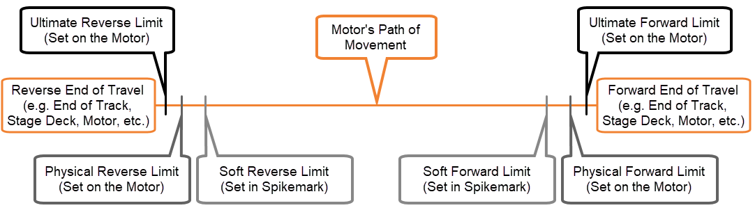
Limits are important. We talk about limits in two ways: **Hard Limits** and **Soft Limits**
### Hard Limits
Physical limits that trigger a stopping response at the Stagehand and prevent the motor from moving. The hard limits should not be used to stop motion when running regular cues.
There are typically two sets of Hard Limits:
1. Initial Limits - set to constrain the travel during the show
2. Ultimate Limits - set at the furthest possible extents of travel to prevent hitting anything else.
### Soft Limits
Software (Soft) limits are set at the farthest extent of unit travel for cued motion. If you don’t have a specific location for these and pace and travel allows, we recommend setting the soft limits at least several inches inside your hard limits.
{% hint style="danger" %}
Soft Limits only prevent you from writing cues beyond this value, you still can [jog](/docs/spikemark/quickstart/jogging.md) your machines beyond this value.
{% endhint %}
When setting limits, use this graphic as a guide to where you should set each limit:
### Limit Indicator in Spikemark
The Triangles in the Axis Info Section shows the status of your limits
* Green - Limit Cleared
* Yellow - Exceeded Soft Limit
* Red - Exceeded Hard Limit
If you Override on a Stagehand Pro 5 or Stagehand Apprentice 2 or more recent, you will see a readout of Limit Overrides in the same area.
## Setting the Spotline Limits
Setting rotary limits can be a trying task. If you are unfamiliar with rotary limits - or what limits are and why there are four on our Spotline - check out this super awesome video we put together about setting limits on the original Spotline hoist:
{% embed url="" %}
We also made a step-by-step slideshow about how to set rotary limits on a Spotline:
{% embed url="" %}
1. Jog the scenery to the location where you want to set the limit
2. E-Stop the Spotline
3. Remove the limit cover
4. Loosen the primary limit screw
5. Adjust your limit with smaller limit screws. We’ve color matched each screw to one of the disks in the stack
1. Ultimate Forward
2. Initial Forward
3. Initial Reverse
4. Ultimate Reverse
{% hint style="info" %}
Forward movement will rotate the stack Clockwise when viewed from the top of the limit stack.
{% endhint %}
Turning the adjustment screws will spin an individual Cam. When setting the hard limit the Cam must actuate the switch on the proper side. This means that the Forward and Forward Ultimate Cams will be on the right of the switch stack and the Reverse and Reverse Ultimate will be on the Left of the switch stack.
* Rotate the cam close to the switch then slowly continue to rotate
* When you hear it \*click\*, very slowly back OFF the limit until you hear it \*click\* again
* EXTREMELY carefully and slowly rotate back onto the switch until it \*clicks\*
Gently re-tighten the primary screw to prevent the cam stack from slipping/changing.
NOTE: Too much torque on this screw can cause the whole cam stack to rotate and drastically change where the limits are tripped
7. Verify that the limit stops the motion where desired
8. Jog the Spotline off the limit (this is usually about 18”-36” inside of where the limit triggered)
9. Jog back onto the limit
10. If it doesn’t stop within the desired tolerance, try again until it stops where you want
11. Repeat steps 3-6 for each hard limit.
12. When all limits are set, it is best practice to go through and re-check all limits to verify that the relationship between all 4 is correct.
## Setting the Cross-Groove
The Spotline V2 is equipped with cross groove detection. A Cross Groove fault is registered when the orange roller moves too far away from the drum. The sensitivity of the two proximity sensors (located at each end of the orange roller) is set at the factory but may need to be adjusted based on the type of lifting line or the diameter of the line.
{% hint style="success" %}
The sensor has a light that turns on when the bar is WITHIN PROXIMITY.
**If the light is out, you will see a X-Groove fault.**
{% endhint %}
 
NOTE: Fibrous rope can often squish enough that it will not reliably trigger a cross-groove without adjusting the sensitivity.
* Decreasing the gap between the arm and the sensor will allow the arm to travel more distance before X-Groove is tripped.
* Increasing the gap will cause the sensor to trip sooner, or even be stuck in X-Groove.
To DECREASE Sensitivity
1. Loosen the nut on the bottom side of the proximity sensor bracket
2. Push the proximity sensor up until it is in the desired position
3. This shifts the gap from between the bottom nut and the brack to the top nut and the bracket
4. Tighten the top nut down onto the bracket to secure the sensor
WARNING: Raising the sensor too high can cause the arm to physically rest (or smash) on the sensor.
WARNING: This can be set high enough that a cross-groove is NOT detected.

To INCREASE Sensitivity
1. Loosen the nut on the top side of the proximity sensor bracket
2. As this nut loosens, gravity will likely pull the sensor down. If it’s stuck on the threads, a gentle wiggle or nudge down should get it to drop
3. Tighten the lower nut onto the bracket to secure the sensor
---
# Agent Instructions
This documentation is published with GitBook. GitBook is the documentation platform designed so that both humans and AI agents can read, navigate, and reason over technical content effectively. Learn more at gitbook.com.
## Querying This Documentation
If you need additional information that is not directly available in this page, you can query the documentation dynamically by asking a question.
Perform an HTTP GET request on the current page URL with the `ask` query parameter, and the optional `goal` query parameter:
```
GET https://docs.creativeconners.com/docs/machinery/spotline-v2/spotline-v2-operation.md?ask=&goal=
```
`ask` is the immediate question: it should be specific, self-contained, and written in natural language.
`goal` is optional and describes the broader end goal you are ultimately trying to accomplish on behalf of the user. GitBook uses it to tailor the answer towards what is most useful for that goal.
The response will contain a direct answer to the question and relevant excerpts and sources from the documentation.
Use this mechanism when the answer is not explicitly present in the current page, you need clarification or additional context, or you want to retrieve related documentation sections.