# Installation
## REQUIRED TOOLS
* Leveling foot square head socket wrench (included)
* 5/32” hex key
* 3/16” hex key
* 3/8” hex key
* 3/8” open end wrench
* 9/16” socket wrench
* 9/16” open end wrench
* 3/4” socket wrench
* 3/4” open end wrench
* 15/16 socket wrench
* 15/16” open end wrench
## UNPACKING THE FLOORPOCKET
The Floorpocket ships from the factory on a custom pallet. A pallet jack is helpful and is what we use in the shop to move the palletized machine around. Once the Floorpocket is roughly in its desired location, the following steps are required to begin operation.
1. Remove any accessories from the Floorpocket platform.
2. Remove the plywood guards on the front, sides and rear of the Floorpocket. The guards are attached with carriage bolts and wing nuts.
3. If the Mast Extension is on the same pallet:
4. Attach a lifting line to the top of the Mast Extension
5. Remove the banding holding the mast extension to the base frame.
6. Remove the mast extension from the base frame, setting aside the plywood guards behind and beneath the mast extension
7. If the Mast Extension is shipped on a seperate pallet:
8. Remove the banding holding the mast extension to the pallet
9. Move the Mast Extension to the lift location - it may be helpful to attach a lift line to move the Mast Extension around.
10. Follow the steps to install the Mast Extension below
NOTE: Removing the mast extension requires careful consideration – not only of the pick points, but also the lifting method and the safety of any person in the vicinity of the lift. Mast extensions may weigh over 350lb. Safe rigging practices are an essential part of this process. This process should only be completed by a qualified rigger.
## PLACING THE FLOORPOCKET
The Floorpocket base configuration includes (4) removable casters for moving the unit without a pallet-jack, but the casters should not be used while operating the lift. To install the casters, use the included 5/8” GR8 Hex Head Bolts with the included threaded ModTruss Washer Plates. Each Caster will use (2) threaded ModTruss Washer Plates, (4) Grade 8 5/8” Hex Head Bolts, and (4) Grade 8 5/8” Washers.
In addition to having (4) casters, (4) removable and adjustable feet are included with your Floorpocket. Both the casters and feet are bolted through the base frame, see the details below. To install the leveling feet, use the included Grade 8 5/8” Hex Head Bolts with the included threaded ModTruss Washer Plates. Each Caster will use (2) ModTruss Washer Plates, (4) Grade 8 5/8” Hex Head Bolts, and (4) Grade 8 5/8” Washers.
Once the Floorpocket is moved into place, level the machine by adjusting the leveling feet with the included 1” square head socket wrench. The bottom of the adjustable foot bracket can be no higher than 5” from the floor. It is the responsibility of the installer to determine the structural integrity of the venue floor. Depending on the installation circumstances, it may be necessary to modify the structure to accommodate the Floorpocket.
|  |  |
| ------------------------------------------------------------------------------------------------------------------------------------------------------------------------------------------------- | ------------------------------------------------------------------------------------------------------------------------------------------------------------------------------------------------- |
## EXTENDING THE FLOORPOCKET
Extension Towers can be bolted onto the Base Tower to extend the overall height from 6’ up to 18’. Follow the steps below to extend the Floorpocket mast.
NOTE: Attaching a mast extension requires a coordinated effort with at least (3) individuals, and involves raising and suspending the mast extension over the heads of several of those individuals. Mast extensions may weigh over 350lb. Safe rigging practices are an essential part of this process. This process should be completed by a qualified rigger.
1. Clear the area around the Floorpocket and lifting machinery, and confirm overhead clearance.
2. Lift the mast extension into position above the Floorpocket base frame mast.
3. Lower the mast extension onto the base frame mast, using the (4) locator pins as guides.

1. Confirm the toothed face of the gear rack and the inner faces of the guide rails are flush at the seam.


1. Connect the gear rack to the top mast bracket with the included 1/2” Socket-head cap screw, rack spacer, washer, and Nylock nut. With ⅜” hex key and ¾” socket.


1. Connect the guide rails to the top mast tower bracket using the (4) included 3/8” low-head cap screws, washers and Nylock nuts.

1. Use the included sets of 5/8” x 2” hex head cap screws, washers and nuts, along with the 12” ModTruss washer plates to attach the mast extension ModTruss to the base frame.

1. Connect the top mast bracket to the top of the upper mast section and secure it using the included (4) Grade 8 5/8” x 1-1/4” hex-head bolts, washers and nuts.

1. Attach mast cap with included 5/8” x 1-1/4” hex head bolts, washers and nylock nuts.

1. Confirm the surfaces from step 4 are still flush, and all connections are tightened to the following torques:
* 3/8” hardware – 23 ft-lb
* 1/2" hardware – 57 ft-lb
* 5/8” hardware – 112 ft-lb
To prevent Tip-over Hazards, the Floorpocket is required to be connected at the top of the mast, no matter the configuration. The top connection must be able to withstand a constant load of 600 lbs in all directions.
?alt=media)
Any additional platforming must not overhang the lifting platform unless consulted through Creative Conners, Inc. with approved engineering review, and all additional platforms should be attached to the lifting platform through the four mounting holes provided.
To prevent Entanglement Hazards, install the included and attached Mast Tower Machine Guard.
?alt=media)
This guard must be installed to prevent any entanglement of props, costumes, or humans in the drive rack. This guard also has the added benefit of keeping the grease from the drive rack away from those priceless costumes. The Floorpocket comes with the Mast Tower Machine Guard preinstalled to the platform. Simply raise the reatracting guard to the top of the mast and secure the guard to the top of the mast. Slide the mounting bracket between the top plate and the top guide rail bracket. Attach with ¼”-20 x 1” Button Head Cap Screw into the threaded holes. The graphic below shows where the guard should cover the Mast Tower.

###
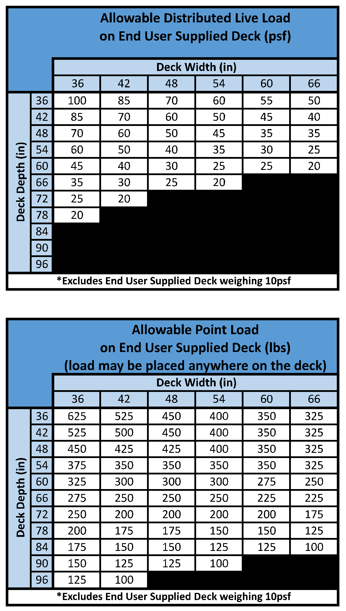
## INSTALLING A LARGER PLATFORM
Use the load table below when determining the load capacity for a larger platform. If you have any questions regarding the capacity of the lift with a larger planform, give us a call or drop us a line at Phone: 401-289-2942 x2 or Email: .

---
# Agent Instructions: Querying This Documentation
If you need additional information that is not directly available in this page, you can query the documentation dynamically by asking a question.
Perform an HTTP GET request on the current page URL with the `ask` query parameter:
```
GET https://docs.creativeconners.com/docs/machinery/floorpocket/installation.md?ask=
```
The question should be specific, self-contained, and written in natural language.
The response will contain a direct answer to the question and relevant excerpts and sources from the documentation.
Use this mechanism when the answer is not explicitly present in the current page, you need clarification or additional context, or you want to retrieve related documentation sections.