Docs
Download Spikemark
  • Creative Conners Docs
  • Technical Support
    • Tech Tips
      • Revolver V1 Position Issues
      • Setting Up a New Comptuer for Spikemark
  • Spikemark 6
    • Navigating Spikemark
      • Show Modes
      • Workspaces
        • Jog Workspace
        • Cues Workspace
        • Preset Workspace
        • Customize Your Workspace
      • Selection and Input
      • Tags
      • Filters
      • Search
      • Keyboard Shortcuts
    • Cues
      • Cue Structure
      • Cue Creation
        • Add Movements
        • Add Triggers
        • Add Actions
      • Editing Cue Properties
      • Cue Deletion
    • Movements
      • Motor Movements
      • Locked Group Movements
      • Unlocked Group Movements
      • FX Movements
      • OSC Movements
        • Custom OSC Command Library
      • UDP Movements
      • Modbus Movements
    • Triggers
      • Playback Go Trigger
      • Delay Trigger
      • Completion Trigger
      • Position Trigger
      • FX Input Trigger
      • Stacking Triggers
    • Actions
      • Motor Property Action
      • Motor Method Action
      • Playback Property Action
    • Running Cues
      • Playbacks
        • Playback Editing
        • Playback Control Speed
        • Playback Stacking
      • Cue Controls
      • Consolette
      • Restore Cue
    • Spikes
      • Simple Spikes
      • Dynamic Spikes
        • Incremental Spikes
        • Nearest Forward Multiple Spikes
        • Nearest Reverse Multiple Spikes
        • Nearest Multiple Spikes
      • Locked Group Spikes
    • Presets
      • Presets Overview
      • Creating, Editing, and Deleting Presets
      • Running Presets
    • User Authentication and Authorization
      • Overview
      • Users
      • Roles
      • Permissions
    • Show Control
      • Open Sound Control (OSC)
        • Send OSC Messages
        • OSC Position Output
        • OSC Input Trigger
          • OSC Input Messages
          • Cue Messages
          • Playback Messages
          • Sequence Step Messages
          • Motor Movement Messages
          • Motor Messages
        • Troubleshooting OSC
          • OSC Response Window
          • Medialon Manager Configuration
      • UDP
        • Send UDP Messages
        • UDP Position Output
      • Watchout Position Output
      • PosiStageNet (PSN)
  • Spikemark 5
    • How to Open Spikemark
    • Spikemark Installation
      • User Authorization
      • Windows Settings
    • Quick Start Tutorial
      • Step 1: Adding Motors
        • 1.1 Simulator Mode
        • 1.2 Add Motors from the Machine Library
        • 1.3 Rename Motors
        • 1.4 Add A Group
      • Step 2: Saving
      • Step 3: Jogging
        • 3.1 Single Axis Jogging
        • 3.2 Jogging Multiple Machines (Multi-Jog)
        • 3.3 Move To Position
      • Step 4: Writing Your First Cues
        • 4.1 Cues Workspace
        • 4.2 Add A Movement
        • 4.3 Duplicate A Cue
        • 4.4 Delete A Movement From A Cue
        • 4.5 Edit Movement - Changing Position, Speed, and Time
        • 4.6 Copy to Group
        • 4.7 Cue Total Time
        • 4.8 Load and Run your Cue
        • 4.9 Spikes
        • 4.10 Cue Links
        • 4.11 Restore Cue
        • 4.12 Delete A Cue
      • Step 5: Going Live
        • 5.1 Set Your IP Address
        • 5.2 Test Manual Movement
        • 5.3 Resetting Position
        • 5.4 Program Your Show
      • Sharpen Your Programming Skills
    • Steps to a Successful Load-In
    • Show Modes
    • Locking Changes
    • Workspaces
      • Customize Your Workspace
    • Selection and Input
    • IP Address and Network Connection
      • Setting Computer IP Address
      • Setting Stagehand IP Address
      • Setting Showstopper Consolette IP Address
      • Setting Pendant IP Address
      • Setting Showstopper IP Address
      • Setting Showstopper Node ID
      • Connecting To A Stagehand
      • Connecting To A Showstopper Consolette
      • Connecting To A Pendant
    • Adding Motors or Machines
      • Adding Motors or Machines From The Machine Library
      • Adding Custom Motors or Machines To Spikemark
      • Importing Motors or Machines
      • Exporting Motors or Machines
    • Stage Model Viewer
      • Changing Your Viewer
      • Adjusting the Stage Size
      • Changing the Type of Scenery
      • Adjusting Model Dimensions
      • Adjusting Model Rotation
      • Adjusting Location On Stage
      • Making Models
        • Modeling A Winch
        • Modeling A Lift
        • Modeling A Hoist
        • Modeling A Vertical Curtain
        • Modeling A Split Curtain
        • Modeling A Turntable or Periaktos
    • Tags
    • Editing Direction Labels
    • Filters
    • Search
    • Position
      • Reset Position
      • Units
      • Position Scale
        • Position Scale Wizard
        • Manually Calculate Position Scale
      • Limits
        • Setting Hard Limits
        • Setting Soft Limits
      • Target Tolerance
      • Strict Timing Mode
      • Position Fault and Max Position Error
      • Motor Tuning Overview
        • Motor Tuning - The Practical Approach
    • Load Cell
      • Load Cell Readout
      • Load Cell Configuration
      • Load Cells and Groups
    • Speed
    • Spikes
      • Adding A Spike
      • Removing A Spike
      • Spike Input Fields
      • Simple Spike
      • Incremental Spike
      • Nearest Forward Multiple Spike
      • Nearest Reverse Multiple Spike
      • Nearest Multiple Spike
    • Editing Cues
      • Adding and Deleting Cues
      • Adding and Deleting Movements
      • Edit Movement
      • Edit Cue Options
    • Cue Controls
    • Cue Status
    • Cue Links
      • Completion Link
      • Time Link
      • Position Link
      • Input Link
      • Deleting A Cue Link
    • Presets
    • Motor Groups
    • Showstopper Node Editor
    • Show Control
      • Open Sound Control (OSC)
        • OSC Position Output
        • OSC Messenger
          • Expanding The Command Library
        • OSC Response Window
        • OSC Input Trigger
          • Input Messages
          • Cue Commands
          • Motor Commands
          • My OSC Input Trigger Isn't Working, Is there another way?
      • UDP
        • UDP Position Output
        • UDP Messenger
      • Watchout Position Output
      • Modbus Effect
      • PosiStageNet (PSN)
    • Drive Communication
      • Drive Information
      • Configuring The Drive
      • Analyzing Movements
      • Drive Communication: Compatibility
      • Drive Communication: Setting VFD Parameters
      • RS-485 Upgrade
        • Upgrading an A800
        • Upgrading an A700
        • Drive Communication Troubleshooting
      • VFD Fault Codes
    • Motor Status Icons
    • Keyboard Shortcuts
    • Advanced Cue Techniques
  • Showstopper
    • Showstopper 4 Base
      • Installation
      • Operation
      • Troubleshooting
      • Specifications
    • Spikemark Console
      • Making-The-Connections
      • Using-the-Console
      • Console-Firmware
      • Troubleshooting
      • Specifications
    • Spikemark Pendant V2
      • Getting Started
      • Setup
      • Operation
      • Troubleshooting
      • Specifications
      • Drawings
    • Showstopper 4 E-Stop Hub
      • Getting Started
      • Installation
      • Operation
      • Troubleshooting
      • Specifications
    • Showstopper 4 Accessory Hub
      • Getting Started
      • Installation
      • Operation
      • Troubleshooting
      • Specifications
    • Showstopper Remote E-Stop
      • Installation
      • Making The Connections
      • Operation
      • Troubleshooting
      • Specifications
    • Control Connection
      • Installation
      • Making The connections
      • Operation
      • Troubleshooting
      • Specifications
    • Drive Connection
      • Installation
      • Making The connections
      • Operation
      • Troubleshooting
      • Specifications
    • Showstopper E-Stop Patch Panel
    • Showstopper Accessory Patch Panel
    • 🦺Safety Interlock
      • Safety Interlock Classic
      • Safety Interlock Pro
      • Safety Interlock Pro 4
      • 4-Axis Safety Interlock
    • Legacy
      • Showstopper 3 Base
      • Showstopper 3 Remote
      • Showstopper 3 E-Stop Patch Panel
      • Stage Manager
        • Getting Started
        • Installation
        • Making the Connections
        • Operation
        • Troubleshooting
        • Specifications
      • Showstopper 4 Consolette
        • Features
        • Making the Connections
          • Accessory Cable Connection
          • Ethernet Connection
          • Multiple Consolettes
        • On-Board Settings
        • Operation & Spikemark Integration
        • Connecting the Consolette to Spikemark
        • Jogging Motors
        • Running Cues
        • Emergency Stop
        • Updating Consolette Firmware
        • Troubleshooting
        • Physical Specifications
        • Drawings
  • Stagehand
    • Stagehand Firmware
      • Manually Updating a Stagehand Unipolar V6 Card via SD Card
      • Manually Updating a Stagehand Unipolar V6 Card via USB
    • Stagehand Parameters
      • Stagehand Pro 2 Parameters
      • Stagehand Pro 3/Pro 4 Parameters
      • Stagehand Pro 3e Parameters
      • Stagehand Pro 5 Parameters
      • Stagehand Apprentice 2 Parameters
      • Stagehand Apprentice
      • Stagehand AC - AKA: The Classic
      • Classic+ Parameters
      • Pro+ Parameters
      • Setting the C3 Value
      • Setting the C4 Value
      • All Clear/Parameter Clear
      • How to Use the Mitsubishi VFD Keypad
      • USB Parameter Sets
      • Parameter Library in Spikemark
    • Stagehand Apprentice
      • Getting Started
      • Installing the Stagehand
      • Making the Connections
      • Hooking up a motorized effect
      • Using the Stagehand
      • Troubleshooting
      • Technical Support
      • Specifications
    • Stagehand Apprentice DC
    • Stagehand Apprentice 2
      • Stagehand Apprentice 2: Features
      • Stagehand Apprentice 2: Installation
      • Stagehand Apprentice 2: Making The Connections
        • Stagehand Apprentice 2: Power Input
        • Stagehand Apprentice 2: Motor and Brake Output
        • Stagehand Apprentice 2: Sensor Input
        • Stagehand Apprentice 2: Interlock Inputs
        • Stagehand Apprentice 2: Ethernet Input
        • Stagehand Apprentice 2: Showstopper Emergency Stop Input
      • Stagehand Apprentice 2: Operation
      • Stagehand Apprentice 2: Troubleshooting
      • Stagehand Apprentice 2 Specifications
      • Stagehand Apprentice 2: Drawings
    • Stagehand FX
      • Getting Started
      • Making the Connections
      • Connecting an Effect
      • Operation
      • Troubleshooting
      • Specifications
    • Stagehand Hydraulic
      • Getting Started
      • Features
      • Installation
      • Operation
      • Troubleshooting
      • Technical Support
      • Specifications
      • Drawings
    • Stagehand Pro 3
    • Stagehand Pro 3E
    • Stagehand Pro 4
      • Stagehand Pro 4: Unpacking
      • Stagehand Pro 4: Installation
      • Stagehand Pro 4: Making The Connections
        • Stagehand Pro 4: Power Input
        • Stagehand Pro 4: Motor and Brake Output
        • Stagehand Pro 4: Sensor Input
        • Stagehand Pro 4: Interlock Inputs
        • Stagehand Pro 4: Ethernet Input
        • Stagehand Pro 4: Showstopper Emergency Stop Input
      • Stagehand Pro 4: Operation
        • Stagehand Pro 4: Powering Up
        • Stagehand 4: Machine Configuration
        • Stagehand Pro 4: Manual Operation (Jogging)
        • Stagehand Pro 4: Brake Test
        • Stagehand Pro 4: Connecting to Spikemark
        • Stagehand Pro 4: Status Displays
      • Stagehand Pro 4: Troubleshooting
        • Stagehand Pro 4: Recovering From Faults
        • Stagehand Pro 4: Monitoring Behavior
      • Stagehand Pro 4: Specifications
      • Stagehand Pro 4: Drawings
    • Stagehand Pro 5
      • Stagehand Pro 5: Features
      • Stagehand Pro 5: Installation
      • Stagehand Pro 5: Making The Connections
        • Stagehand Pro 5: Power Input
        • Stagehand Pro 5: Motor and Brake Output
        • Stagehand Pro 5: Sensor Input
        • Stagehand Pro 5: Interlock Inputs
        • Stagehand Pro 5: Ethernet Input
        • Stagehand Pro 5: Showstopper Emergency Stop Input
      • Stagehand Pro 5: Operation
      • Stagehand Pro 5: Troubleshooting
      • Stagehand Pro 5 Specifications
      • Stagehand Pro 5: Drawings
      • Stagehand Pro 5: Replace Control Card
    • Deck Chief 2
      • Getting Started
      • Features
      • Making the Connections
      • Using the Deck Chief
      • Troubleshooting
      • Specifications
    • Stagehand Classic+
    • Stagehand Pro+
    • Legacy Manuals
      • Deck Chief
        • Getting Started
        • Installation
        • Making the Connections
        • Using the Deck Chief
        • Troubleshooting
        • Specifications
        • Deck Chief Legacy Connections
      • Stagehand Mini^2
      • Stagehand Pro AC (Pro 2)
      • Stagehand AC
      • Stagehand Mini
      • Stagehand DC & DC Max
    • X-Groove Override
  • Machinery
    • Smart Chain Hoist
      • Getting Started
      • Installation
      • Making the Connections
      • Under The Hood
      • Troubleshooting
      • Specifications
    • Floorpocket
      • GettingStarted
      • Installation
      • Making the Connections
      • Prepping the Machine for Operation
      • VFD Settings
      • Troubleshooting
      • Specifications
    • Floorpocket v2
      • Get Started
        • Unpack
        • Installation Tools
      • Assembly
        • Base
        • Column Extension
        • Limit Cables
        • Roller Chain
      • Get Moving
        • Power Up
        • Platform
        • Stay Safe
        • Write Cues
      • Maintain the Machine
      • Troubleshooting
      • Floorpocket v2: Specifications
    • Pivot
      • Getting Started
      • Installation
      • Troubleshooting
      • Specifications
    • Pushstick
      • Getting Started
      • Installation
      • Making the Connections
      • Rigging the Pushstick
        • Rigging a Pushstick v2
      • Setting the Limits
      • Troubleshooting
      • Specifications
    • Pushstick Mini
      • Getting Started
      • Installation
      • Making the Connections
      • Rigging the Pushstick Mini
      • Troubleshooting
      • Technical Support
      • Specifications
    • Revolver
      • Installation
      • Making the Connections
      • Making It Move
        • Friction Wheel Tension Guide
      • Position Scaling
        • Encoder Finessing
      • Troubleshooting
      • Specifications
        • Drawing
      • Multi-Motor Configuration
      • Revolver v1 Manual
    • Rotator
      • Getting Started
      • Installation
      • Making the Connections
      • Troubleshooting
      • Technical Support
      • Specifications
    • Spotline
      • Getting Started
      • Installation
      • Rigging the Spotline
      • Operation
      • Troubleshooting
      • Specifications
    • Spotline V2
      • Spotline V2: Setup Process
      • Spotline V2: Installation
      • Spotline V2: Rigging the Spotline
      • Spotline V2: Operation
      • Spotline V2: Troubleshooting
      • Spotline V2 Accessories
      • Spotline V2: Maintenance
      • Spotline V2: Specifications
    • Spotline Mini v2
    • Spotline Practical
      • Practical v2
        • Getting Started
        • Installation
        • Rigging the Machine
        • Setting the Limits
        • Troubleshooting
        • Specifications
      • Practical v1
        • Getting Started
        • Installation
        • Operation
        • Troubleshooting
        • Specifications
    • Turntable Template
      • Overview
      • Bill Of Materials
      • Fabrication
      • Turntable Assembly and Installation
      • Turntable Assembly Guide
      • Tech Support
      • 20' Turntable Specs
      • Turtable Research Notes for Nerds
    • Retired
      • Curtain Call
      • Trickline
        • TricklineProductManualv1.0
        • Getting Started
        • Installation
        • Making the Connections
        • Troubleshooting
        • Specifications
      • Spotline Mini
        • Getting Started
        • Installation
        • Making the Connections
        • Rigging the Spotline Mini
        • Troubleshooting
        • Specifications
      • Pushstick Manual
    • Stromag Limits
  • Broadweigh Load Cells
Powered by GitBook
On this page
  • MOTOR & BRAKES
  • SAFETY INTERLOCK
  • EMERGENCY STOP CONNECTION
  • SAFETY SENSORS CONNECTIONS
  • INTERLOCK AGGREGATOR BOX
  • SAFETY MAT
  • PLATFORM SAFETY BUMPER SWITCHES
  • TRAP EDGE SAFETY BUMPER SWITCHES
  • AUXILIARY SAFETY SENSOR
  • SIGNAL CONNECTIONS
  • LIMITS
  • INTERLOCK AUXILIARY LIMIT SWITCHES

Was this helpful?

  1. Machinery
  2. Floorpocket

Making the Connections

PreviousInstallationNextPrepping the Machine for Operation

Last updated 2 years ago

Was this helpful?

The Floorpocket lift requires a Stagehand Pro AC and a Safety Interlock Box for operation. The Stagehand Pro AC has several key safety features not found in other Stagehand controllers that are critical for safe operation.

  • Closed Loop vector mode for full-torque at zero-speed control

  • Overspeed detection

  • Safety Relay

  • Ultimate Limit inputs

  • Dual brake control

MOTOR & BRAKES

Connect the Pro Motor Cable manufactured by Creative Conners, Inc to carry power for the motor and brake from the Stagehand Pro AC to your Floorpocket Junction Box. We use a Harting IRC latching hood style connector for the Pro Motor Cable to ensure that your machine stays connected during operation.

SAFETY INTERLOCK

You may be thinking, “wait, don’t we have all the safety we need already?”. Unfortunately a stage lift requires many safety features to keep everyone safe. These additional systems include bumper switches, safety mats and auxiliary limits, which are incorporated through the Safety Interlock Box.

The Safety Interlock Box sits between the Stagehand Pro AC and the Floorpocket, reading signals from the safety sensors and interrupting motion if any safety sensor is activated.

  1. Three indicator lights to show the status of the Safety Interlock

  2. Signal input from the Stagehand Pro AC

  3. Signal output to the Floorpocket

  4. Aux Limit connections, two each:

    1. Ultimate, Forward, Reverse

  5. Forward and Reverse sensors (one input and output for each direction)

  6. Emergency Stop input and through

EMERGENCY STOP CONNECTION

The Safety Interlock Pro requires a +24VDC Emergency Stop signal from a Showstopper 3 Base or Hub in order to allow motion. This +24VDC powers an internal safety relay, and you can daisy chain through to the Stagehand motion controller. The 5-pin XLR cable is not a DMX signal, but rather it was chosen as a convenient cable that is prevalent in many venues so you should always be able to find a spare cable when needed.

Below is the pin-out for the Emergency Stop input - polarity is important:

SAFETY SENSORS CONNECTIONS

The Safety Interlock Pro adds additional support for 4 wire safety circuits (e.g. bumper switches, pressure mats). A 4 wire safety circuit, when used in conjunction with a safety relay, allows monitoring for the following four conditions:

  1. Disconnected – The safety relay sends out test pulses through the sensor and expects the signal to return. If that signal does not return the safety relay will go into a faulted state and disallow any further motion.

  2. Shorted – If a wire has been crushed by equipment or cut the safety relay will go into a faulted state.

  3. Cross Circuit – If the signals get crossed and the test pulse comes back on the opposite channel the safety relay will go into a faulted state.

  4. Good – If none of the above conditions occur the safety relay will not prohibit any movement.

There are 4 sets of safety sensors that are designed to be connected with the Floorpocket and the Safety Interlock Box.

  1. Safety Pressure Mat (REV Safety Sensor)

  2. Platform Safety Bumper Switches (REV Safety Sensor)

  3. Trap Edge Safety Bumper Switches (FWD Safety Sensor)

  4. Auxiliary Safety Sensors (optional)

INTERLOCK AGGREGATOR BOX

The Interlock Aggregator Box is located inside the ModTruss frame of the Floorpocket. The Interlock Aggregator Box distributes the signal for the REV Safety Sensor of the Safety Interlock Box. Below are graphics that show how you should connect into the Interlock Aggregator Box and how the Interlock Aggregator Box is wired:

SAFETY MAT

To prevent a Crush Hazard when the lift is lowering, we include a Safety Mat to stop the machine from running if there is pressure applied to the Safety Mat.

Install the Safety Mat by placing the Safety Mat under the platform and plugging both 3-pin XLR connectors into the Interlock Aggregator Box located inside the ModTruss Bottom Frame.

PLATFORM SAFETY BUMPER SWITCHES

To prevent a Severing Hazard while the lift is lowering, we include Safety Bumpers already attached to the platform.

Simply verify that all 4 Safety Bumper Switches attached to the platform are connected together and wired to the Interlock Aggregator Box located inside the ModTruss Bottom Frame.

TRAP EDGE SAFETY BUMPER SWITCHES

To prevent a Crushing Hazard while the lift is rising, we included Safety Bumper Switches for you to install around the opening of your stage.

To install your Trap Edge Safety Bumper Switches, slide the rubber bumper out of the aluminum mounting bracket. Use the holes in the mounting bracket to fasten the mounting bracket to the bottom side of the stage. Attach the mounting brackets around the perimeter of your stage opening, using the fasteners that attach best to your building structure. Then slide the rubber bumper back into the mounting bracket. Lastly, connect the 3-pin XLR connectors together in series and connect into the FWD Safety Sensor Connectors of your Safety Interlock Box.

AUXILIARY SAFETY SENSOR

The Auxiliary Safety Sensor is an additional available way to integrate a REV Safety Sensor. You may wonder why you would need an additional REV Safety Sensor. In some situations, you may need a larger platform than the stock 3ft x 3ft platform. If you do need a larger platform, please consult us here at Creative Conners, Inc. to make sure the new platform fits within the engineered specifications. With a larger platform, you will need to add an additional set of Safety Bumper Switches to the larger platform to prevent a Severing Hazard while the lift is lowering. If you are not using the Auxiliary Safety Sensor, make sure the included Interlock Jumper Cable is inserted into the Interlock Aggregator Box.

SIGNAL CONNECTIONS

Two sets of encoder signals (one for speed monitoring and one for positioning) and three sets of limit switch signals (forward, reverse, and ultimate) are combined in one cable with a bulkhead connector (ILME CDDF-24). Encoders are powered at 5vdc for broadest compatibility.

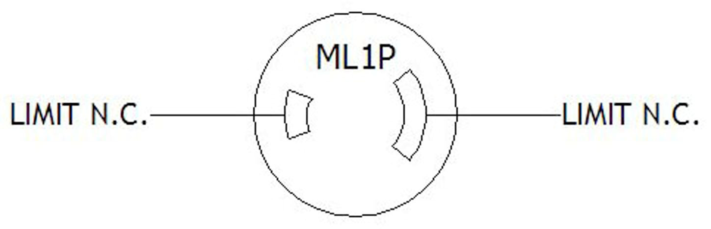
All limit switch signals require Normally Closed (N.C.) switches. The Stagehand Pro AC sources 12vdc on a pin of each limit circuit and expects to see that 12vdc signal returned on the other pin when the limit is not activated. If the limit is either activated or disconnected, or a wiring fault occurs, the 12vdc return signal is interrupted and the Stagehand Pro AC will enter a limit fault condition and disallow motion.

The limit switch inputs are used to protect against the motor traveling too far in either direction and causing damage or injury. When running in a cue, this is one of the safety features that guards against overtravel due to encoder failure. When jogging manually, this keeps you from accidentally traveling too far. Limit switches use NEMA ML1 connectors.

The signal cable for the Floorpocket must be run through the Safety Interlock Box from the Stagehand Pro AC to operate. This means that you will need two signal cables. One to connect the Stagehand Pro AC to the Safety Interlock Box and a second to connect from the Safety Interlock Box to the Floorpocket.

LIMITS

On the Floorpocket we include a redundant set of end-of-travel limits. Like many of our machines, the Floorpocket come with FWD, REV, FWD ULT, and REV ULT Limits pre-installed on the machine. Below shows the location of each limit. Each limit needs to be plugged into the Limit J-Box.

INTERLOCK AUXILIARY LIMIT SWITCHES

Auxiliary Limits – These limits are wired in series with their corresponding standard limits. Thus, if a Forward Auxiliary limit is activated, the Stagehand Pro AC will read the limit as a Forward Limit. Similarly, if a Reverse Auxiliary limit is activated the Stagehand Pro AC will read the limit as a Reverse Limit. Auxiliary limits use NEMA ML1 connectors.

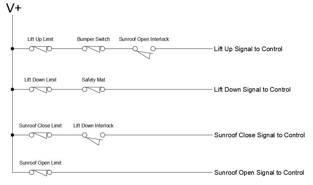
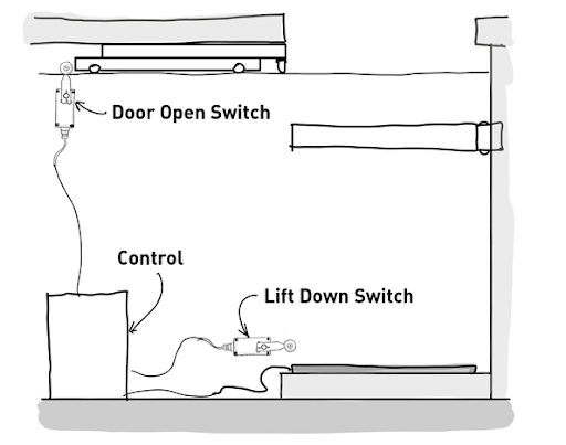
The Auxiliary Limits were originally conceived to be used with a Floorpocket and trapdoor (sunroof) application. This way, if you placed a Normally Open limit switch that is connected to the FWD Aux Limit input of the Stagehand Pro AC in the open position of your trapdoor (sunroof), this would prevent the lift from moving forward (or up) until the trapdoor (sunroof) is open. Similarly, you can do this with the REV Aux Limit to prevent the trap door from closing while the lift is in its raised position by placing a Normally Open limit switch where the limit is struck when the lift reaches its lowest position and is clear of the trapdoor (sunroof). If you are not using a trapdoor (sunroof) with your Floorpocket, you do not need Auxiliary Limits for your system. If you are not using a trapdoor (sunroof) with your Floorpocket, simply insert the included auxiliary limit jumpers to clear the limits. The graphic below shows how the limits could be placed for this system.

The graphic below shows the logic of how the interlock system controls the ability for motion to take place.