> For the complete documentation index, see [llms.txt](https://docs.creativeconners.com/docs/llms.txt). Markdown versions of documentation pages are available by appending `.md` to page URLs; this page is available as [Markdown](https://docs.creativeconners.com/docs/stagehand/stagehand-pro-6/stagehand-pro-6-electrical-installation/stagehand-pro-6-motor-connection.md).
# Stagehand Pro 6: Motor and Brake Output
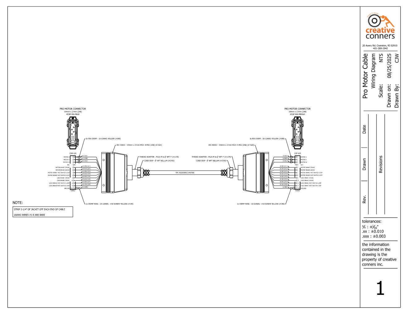
The **Motor / Brake** output receptacle combines power for a motor and two brakes into a single, 12-pin connector.
{% hint style="info" %}
The receptacle has a current rating high enough for 5hp, 10hp, and 20hp machines. However, output capacity is limited by the Variable Frequency Drive (VFD) inside each model of Stagehand Pro.
{% endhint %}
## Motor Output
The motor output is intended for connection to a **3-phase**, **inverter-duty**, **induction motor**. The attached motor should be wired for the correct voltage (see the table at the bottom), and suitable for variable frequency from 0.5Hz-60Hz.
| Pin # | Purpose |
| :---: | -------- |
| 1 | Motor U |
| 2 | Motor V |
| 3 | Motor W |
| 4 | Not used |
## Motor Brake Output
The **Motor Brake** power circuit is a single phase that matches the input power source with a fixed frequency (*typically 60Hz in the United States and 50Hz abroad*).
The **Motor Brake** power circuit is energized \~60ms prior to motion. It should be used to release a quick-acting mechanical brake *(typically on the high-speed side of a powertrain)*. Power is applied during motion and removed when motion stops. The mechanical brake should be a spring-set safety brake that will hold the load when power is removed.
In addition to the power circuit (pins 5 & 6), there is a potential-free / dry-contact circuit that is switched on pins 7 & 8. During motion, there is continuity between pins 7 & 8. When motion stops, the circuit is opened between pins 7 & 8. This circuit can be used to interrupt the DC power on some safety brakes to decrease stopping time and is referred to as the **Fast Switch Loop**.
{% hint style="info" %}
Not all brakes support the fast-brake switching circuit on pins 7 & 8, and not all scenarios require it. This is an optional connection.
{% endhint %}
| Pin # | Purpose |
| :---: | ------------------------------ |
| 5 | Motor Brake L1 |
| 6 | Motor Brake L2 |
| 7 | Motor Brake - Fast Switch Loop |
| 8 | Motor Brake - Fast Switch Loop |
## Load Brake Output
The **Load Brake** power circuit is a single phase that matches the input power source with a fixed frequency (*typically 60Hz in the United States and 50Hz abroad*).
The **Load Brake** power circuit is energized \~800ms prior to motion. It should be used to release a slow-acting mechanical brake *(typically on the low-speed side of a powertrain)*. Power is applied during motion and removed when motion stops. The mechanical brake should be a spring-set safety brake that will hold the load when power is removed.
In addition to the power circuit (pins 9 & 10), there is a potential-free / dry-contact circuit that is switched on pins 11 & 12. During motion, there is continuity between pins 11 & 12. When motion stops, the circuit is opened between pins 11 & 12. This circuit can be used to interrupt the DC power on some safety brakes to decrease stopping time and is referred to as the **Fast Switch Loop**.
{% hint style="info" %}
Not all brakes support the fast-brake switching circuit on pins 11 & 12, and not all scenarios require it. This is an optional connection.
{% endhint %}
| Pin # | Purpose |
| :---: | ----------------------------- |
| 9 | Load Brake L1 |
| 10 | Load Brake L2 |
| 11 | Load Brake - Fast Switch Loop |
| 12 | Load Brake - Fast Switch Loop |
{% hint style="danger" %}
The 6A Max current rating for the **Motor Brake** and **Load Brake** outputs is a combined rating. The power for both brake circuits runs through a single 6A circuit breaker on the front panel of the Stagehand Pro 6.
{% endhint %}
## Power Table
| Stagehand Pro Model | Motor Output Voltage | Motor Output Current | Brake Output Voltage | Combined Brake Output Current |
| :-----------------: | :------------------: | :------------------: | :------------------: | :---------------------------: |
| SHPAC-6-208-3HP | 200VAC - 240VAC | 11.0A | 200VAC - 240VAC | 6A |
| SHPAC-6-208-5HP | 200VAC - 240VAC | 17.5A | 200VAC - 240VAC | 6A |
| SHPAC-6-208-7.5HP | 200VAC - 240VAC | 24.0A | 200VAC - 240VAC | 6A |
| SHPAC-6-208-10HP | 200VAC - 240VAC | 33.0A | 200VAC - 240VAC | 6A |
| SHPAC-6-480-3HP | 380VAC - 480VAC | 6.0A | 380VAC - 480VAC | 6A |
| SHPAC-6-480-5HP | 380VAC - 480VAC | 9.5A | 380VAC - 480VAC | 6A |
| SHPAC-6-480-7.5HP | 380VAC - 480VAC | 12.0A | 380VAC - 480VAC | 6A |
| SHPAC-6-480-10HP | 380VAC - 480VAC | 17.0A | 380VAC - 480VAC | 6A |
---
# Agent Instructions
This documentation is published with GitBook. GitBook is the documentation platform designed so that both humans and AI agents can read, navigate, and reason over technical content effectively. Learn more at gitbook.com.
## Querying This Documentation
If you need additional information that is not directly available in this page, you can query the documentation by asking a question.
Perform an HTTP GET request on the following URL with the `ask` and `goal` query parameters:
```
GET https://docs.creativeconners.com/docs/stagehand/stagehand-pro-6/stagehand-pro-6-electrical-installation/stagehand-pro-6-motor-connection.md?ask=&goal=
```
`ask` is the immediate question: it should be specific, self-contained, and written in natural language.
`goal` is what the user is ultimately trying to achieve, the reason they need the answer. Sharing it helps GitBook give you a better, more relevant answer. A goal is most helpful when it describes the outcome the user wants rather than restating the question. For example, with `ask=how do I create an API token`, a goal like `automate deployments from our CI pipeline` lets GitBook tailor the answer to that use case.
The response will contain a direct answer to the question and relevant excerpts and sources from the documentation.
Use this mechanism when the answer is not explicitly present in the current page, you need clarification or additional context, or you want to retrieve related documentation sections.